- 2021-04-01 — This does not end well ⬿
- 2021-05-01 — Hacking the Rollova: The Nuclear Option
This does not end well
For my birthday, I was given a Rollova 2.0. It is an electronic measuring tape, except that instead of a physical tape, the circumference orbits. The number of revolutions are measured, and converted to a linear distance which is shown on an LCD. It also has the ability to store measurments that the user has taken. It’s a neat gadget, but to me the potential was entirely untapped.
The product’s website advertises that it has an STM32 microcontroller unit (MCU). This is a fairly common family of 32-bit ARM chips made by STMicroelectronics. Inspired by the now famed Doom on a pregnancy test, I determined to hack this thing. After all, it has plenty of inputs: a rotation encoder, and two buttons. That’s gotta be enough to play doom, or at least something simpler like Snake.
The company that produces the Rollova declined to tell me the exact model.
Hi Jonah,
Thanks for your coming.
Your question is related to the strictly confidential technical information which I don’t know either.
Thanks for your kind understanding.
Best regards,
Wouldn’t want anyone to know what kind of chip your measuring tape uses, oh well. I’ll figure it out myself.
Step 1: take it apart
This thing is very easy to disassemble. There is no glue, only a battery panel and 4 screws. It’s just begging to be tampered-with.
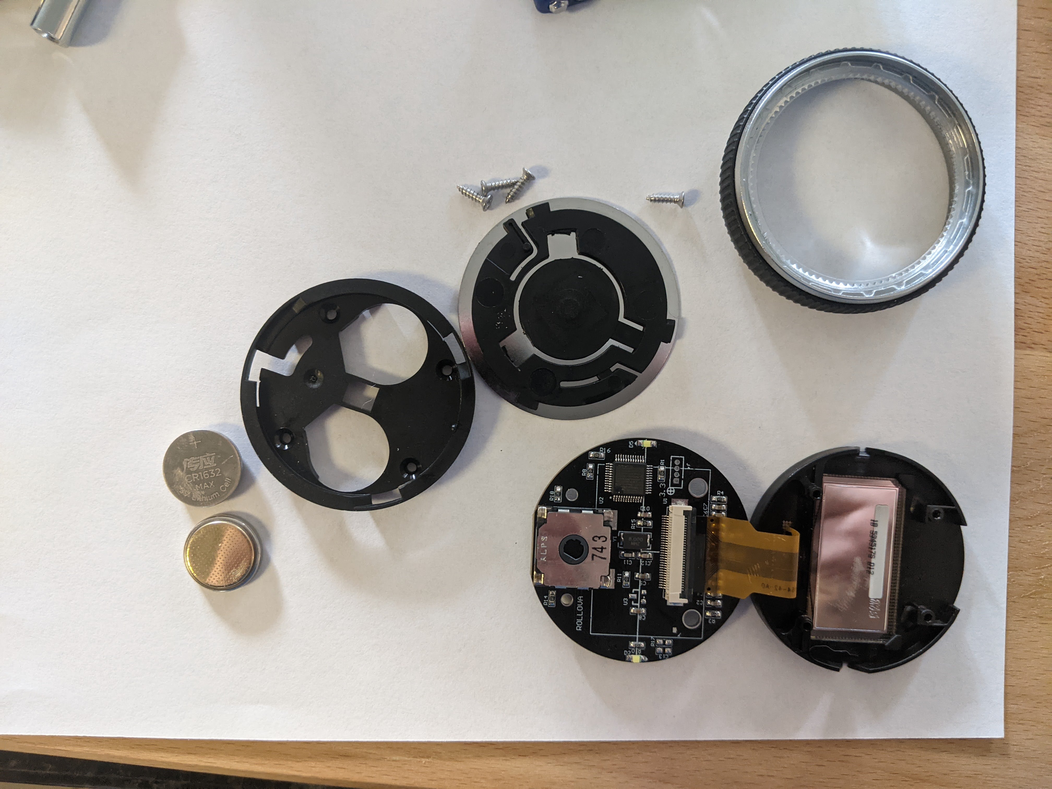
To my dismay, there were no markings on the MCU itself. I had hoped to easly determine the exact model and figure things out from there. Time to do some more general research about how to talk to STM32s. The Electrical Engineering SO couldn’t provide much but a lead: “SWD”.
Step 2: figure out how to talk to it
Some research revealed I needed two things: special software, and special hardware. Not knowing the model doesn’t turn out to be an issue, because ST’s STM32CubeProgrammer can talk to any STM32 MCU. On the hardware side, ST’s ST-LINK/V2 can talk to any STM32 or STM8 (the 8-bit sibling product line). Well this can’t be too bad. I ordered an ST-Link. Both the STM32 and the LINK speak either JTAG or SWD. The remaining issue was how to physically connect to the MCU. This is a tiny chip on a small board; the pins are 0.5mm pitch, and SWD requires 4 pins to operate; I can’t hold all 4 in place by hand, and I don’t want to solder it. A while of searching around turned up a German company called Reichelt that makes a tiny clip called the Challenger clip 6800 for this exact purpose.
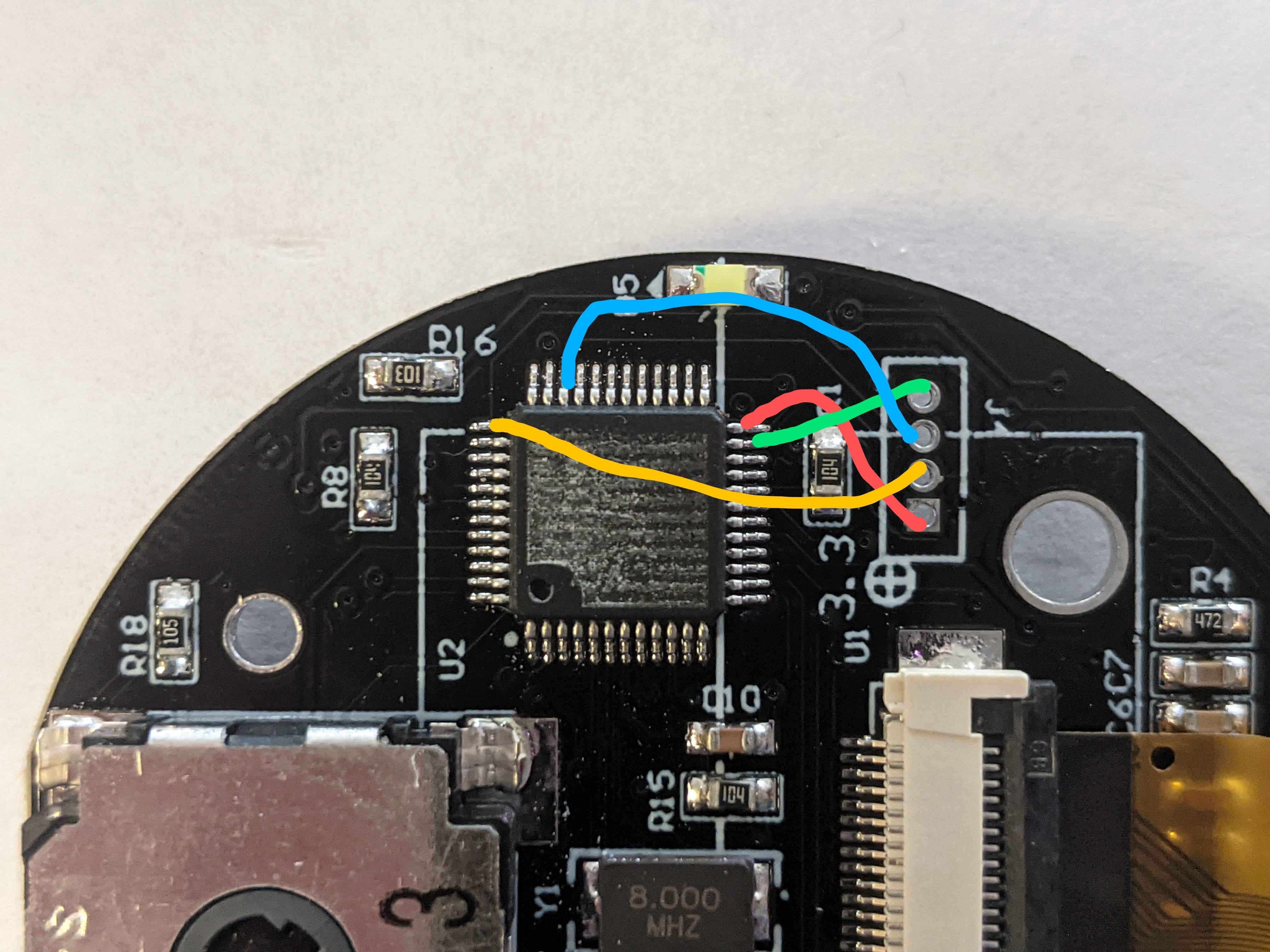
The clips shipped from Germany and took about a month. The Link came much sooner. And while I was looking at that very image of the taken-apart Rollova above, it became clear I had missed something important: it has a hole-thru 4-pin header, the exact number needed for SWD! Not only was this going to make the physical interface much easier, it could make it easier to narrow-down the the model. A bit of fiddling with a continuity tester showed that the pins were in fact connected to the pins assigned to VDD, GND, SCLK, and SWDIO on the STM32L- (the ultra-low-power series, which makes sense for this device). What a breakthrough! The signs were again there that this thing was begging to be hacked: I wouldn’t even need the pin clips.
Obstacles
I quickly found a pin-out diagram of the ST-LINK for SWD, connected to the headers, and clicked “Connect” in STM32CubeProgrammer. “Target not found”. Everything seemed right. I double and triple-checked the orientation of the headers on both the board and the ST-LINK. “Target not found”. I couldn’t believe it. Maybe the configuration options on the programmer are wrong? I updated the LINK’s firmware, and tried every possible connection configuration. “Target not found”.
Some desparate googling revealed a couple of facts.
- Without an additional connection to RST, the programmer cannot reset the chip. This may be necessary if the original program does not allow live debugging.
- Without applying voltage to the boot0 pin upon reset, the chip will start the manufacturer’s program, which might disable the pins necessary for reading/writing.
Neither those pins were exposed in the 4-pin header, so I would need those tiny clips after all.
Dead-end
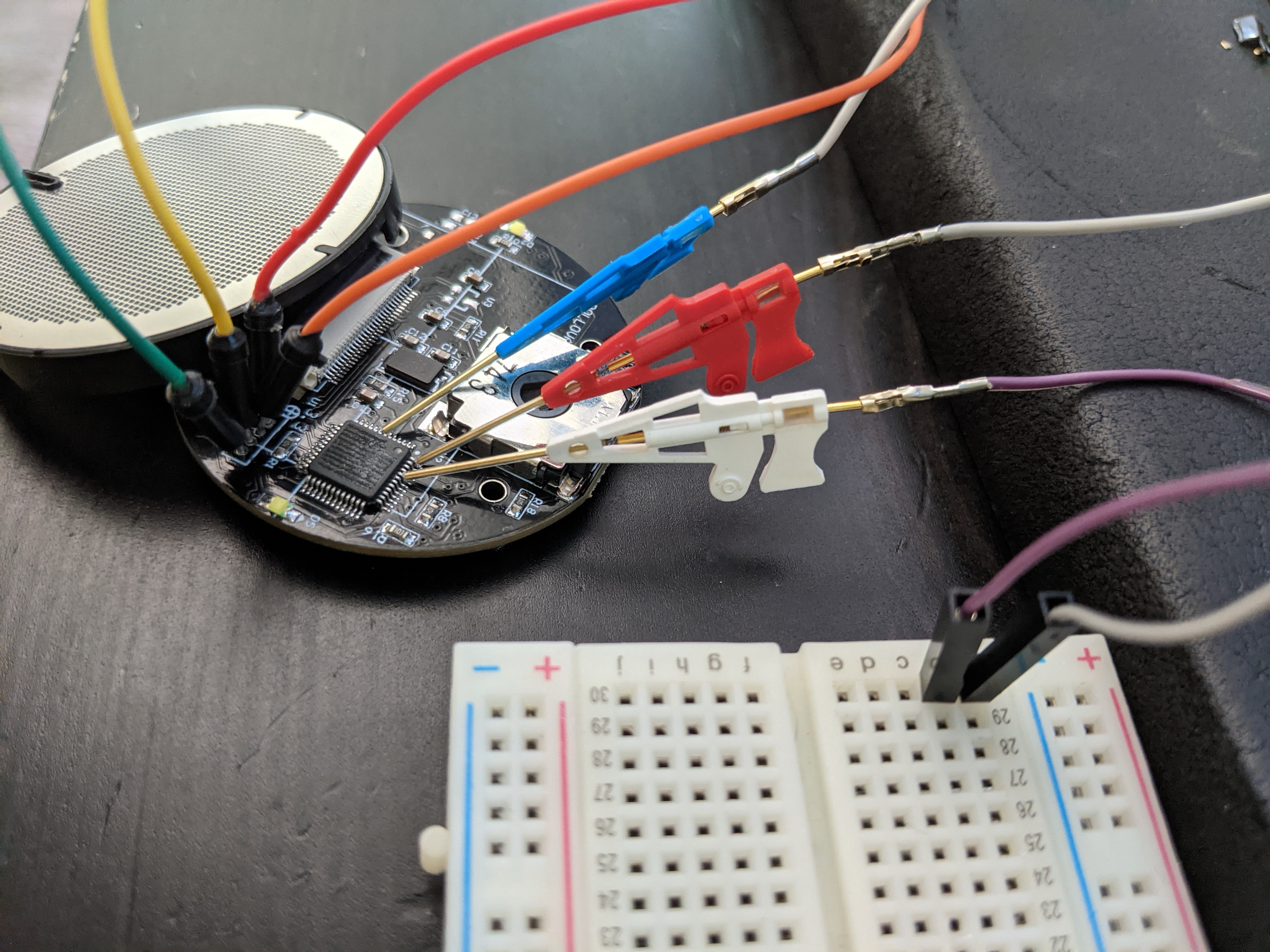
The clips finally crossed the ocean-blue and made it to my doorstep. I hooked them up, convinced that it would work now. The 4 SWD pins, plus the NRST, and tying BOOT0 high had to fix it.
“Target not found”
Some troubleshooting showed that the extra connections were working as expected. When attempting to connect, the MCU would only reset (LEDs blink briefly) if the RST pin was connected. Plus, the normal program would only start (measuring program operates) when BOOT0 was disconnected. Clearly these additional steps were having the desired effect. It simply wouldldn’t connect.
There was nothing left. I verified all continuity, and there were no shorts in the connection. In a desparate last bid, I posted to the ST community forum, hoping for a solution. A single reply revealed the true villain in this story: Intellectual Property.
Something that I had foolishly skimmed over in the datasheet was the “security” section. The STM32 family has a mechanism for preventing read/write of its flash memory after programming: Readout Protection (RDP). In particular, this line has a fuse that can be blown to permanently prevent debug access. Once that is done, only the program that’s already on the MCU has the ability to alter any part of the memory. That seems to be the only explanation.
The end
So that’s it. I’m left with some tools that might come in handy in the future, and a renewed sense that Capitalism is Bad™. For now, this thing will remain a tape measure. The only thing I could possibly do is to make a best guess at an equivalent STM32L model, desolder the current MCU from the board (without destroying it), and re-solder the replacement (again, without destroying it). Maybe I’ll give that a shot at some point.
But for now, I can rest easy knowing that the intellectual property of this measuring tape is safe ♥
Next: 2021-05-01 — Hacking the Rollova: The Nuclear Option
