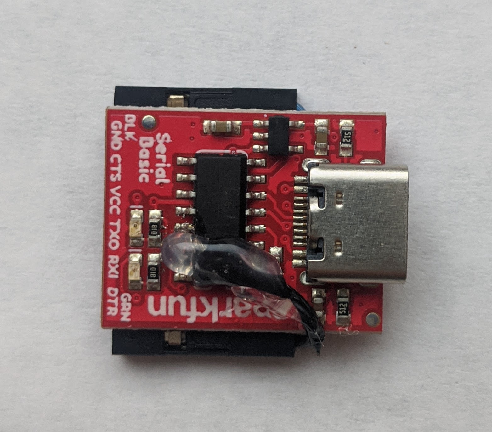
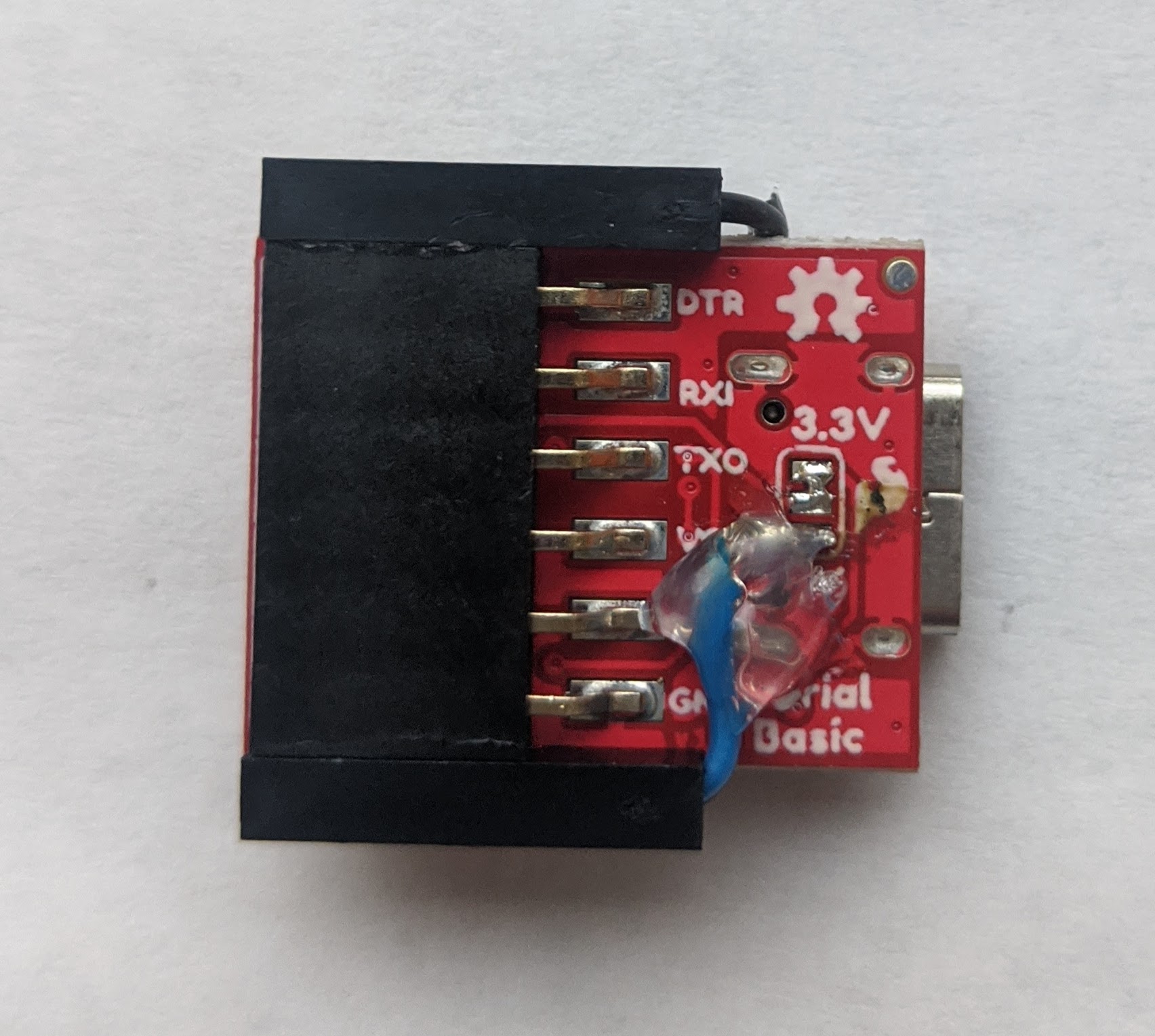
USB Serial Mod
A project I’m working on with the ESP8266 requires a USB module. The one I bought from Sparkfun has a USB C port, and 6 pin-outs.
- TX
- RX
- DTR
- CTS
- VCC
- GND
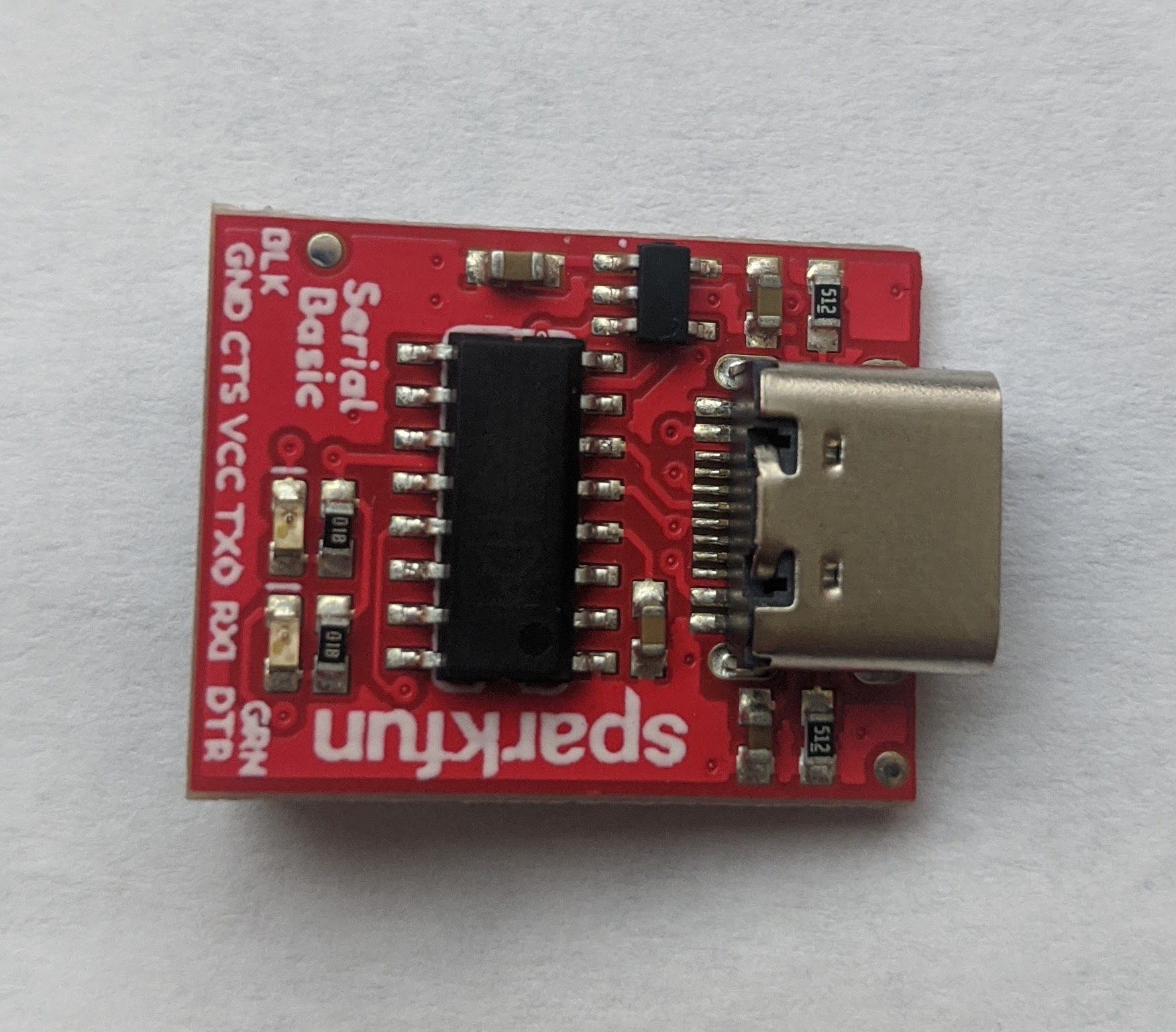
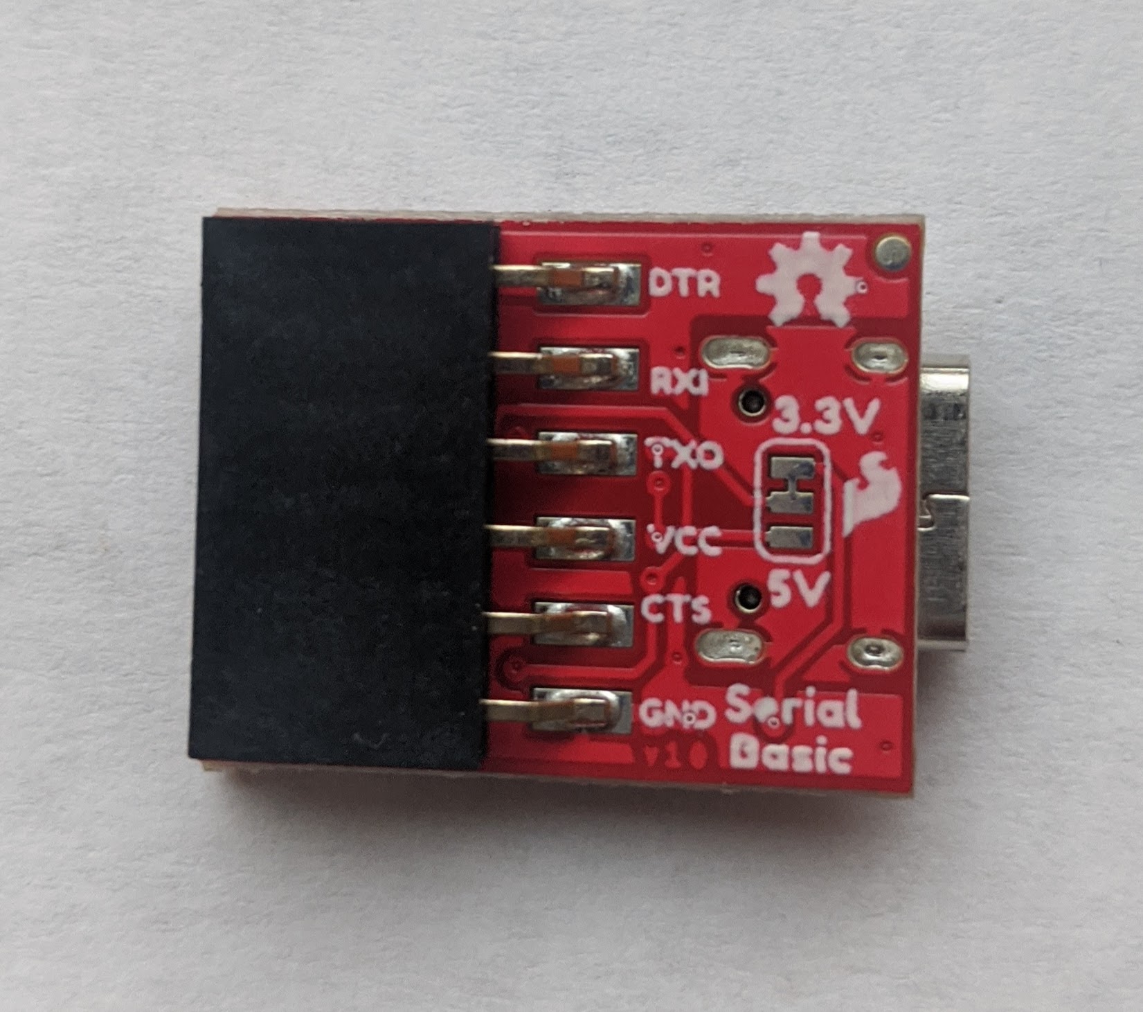
Unfortunately, to be able to wire up the ESP for flashing, the ESP needs access to the RTS pin, which is not made available by this usb/serial breakout. However, the chip itself does have that pin.
With some inspiration from others, and some confirmation of the concept, I decided to add an extra terminal soldered to the correct pin on the chip. I tested by holding the jumper manually, and it worked great.
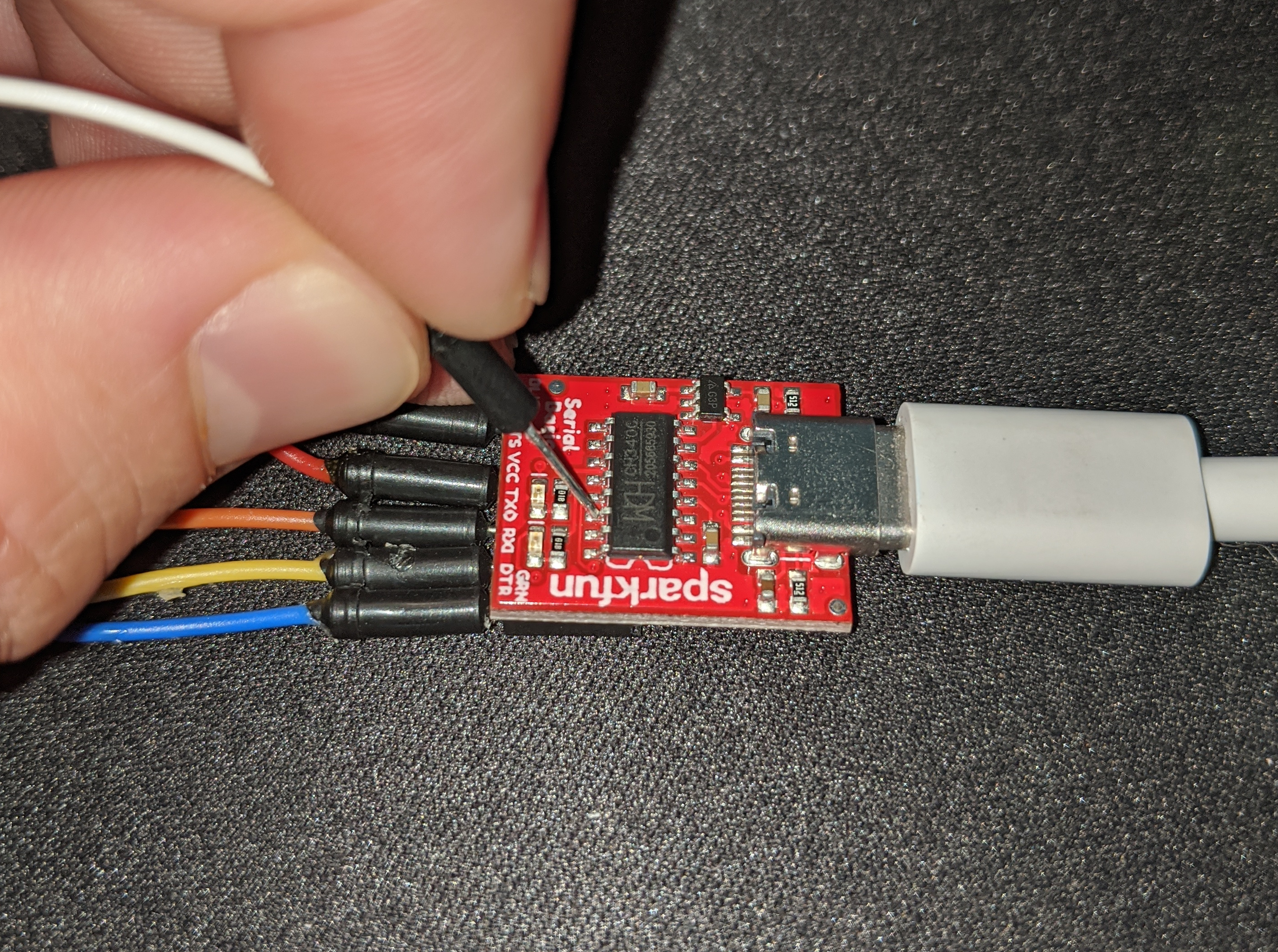
However, the RTS pin is not the only thing I need. This USB module has the ability to operate at either 3.3V or 5V. But while the ESP operates at 3.3V, I need 5V to charge a battery (3.3V will not do this without a voltage amplifier). Fortunately, I can steal the 5V needed from the pad normally intended to switch the module to 5V mode.
With that, I cut and stripped some jumper wires with female terminals, and soldered them in place.
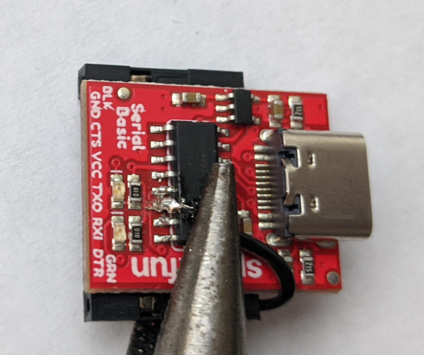
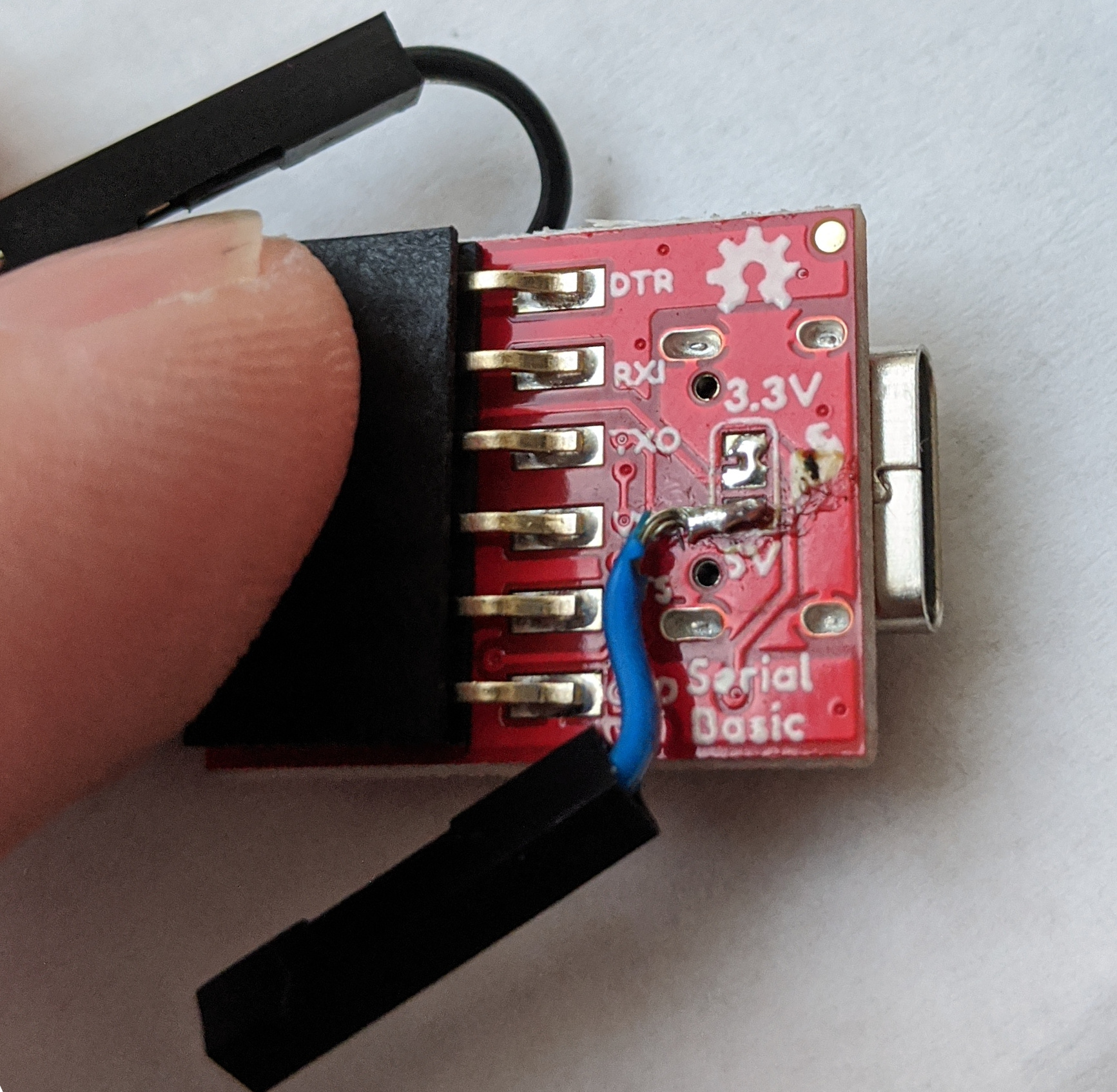
After a test of flashing the ESP with this module and confirming it behaves as expected, I wrapped it up by protecting the new soldered connections with hot-melt glue. I also glued the terminals to the edge of the original serial port, to expand the interface from 6 to 8 pins.
