- 2019-03-21 — Smart Plug Intro
- 2019-03-22 — Smart Plug Prototype 0.1
- 2019-03-22 — Smart Plug Prototype 0.2
- 2019-03-22 — Smart Plug Prototype 0.3
- 2019-03-22 — Smart Plug Prototype 0.4
- 2019-03-27 — Smart Plug Prototype 0.5
- 2019-03-29 — Smart Plug Prototype 0.6
- 2019-04-04 — Smart Plug Prototype 1.0
- 2019-06-05 — Smart Plug Prototype 2.0 ⬿
- 2019-07-14 — Rust on Arduino
- 2019-07-28 — W5500 Driver for Rust Embedded-HAL on AVR
- 2019-07-31 — Working UDP Listener in Rust (finally)
Smart Plug Prototype 2.0
Now that we have a working proof-of-concept, it’s time to take this project into the prototype stage. I’ve demonstrated that the idea can work using off-the-shelf components. Now it’s time to start simplifying and refining the product. That means bye-bye Beaglebone Black, and hello Arduino. An entire computer and OS is wholly unnecessary for a task as simple as this. Arduino is the most popular (and best supported) platform of which I’m aware for developing embedded systems. There may be a point at which this project outgrows even that, but for now it will do what we need.
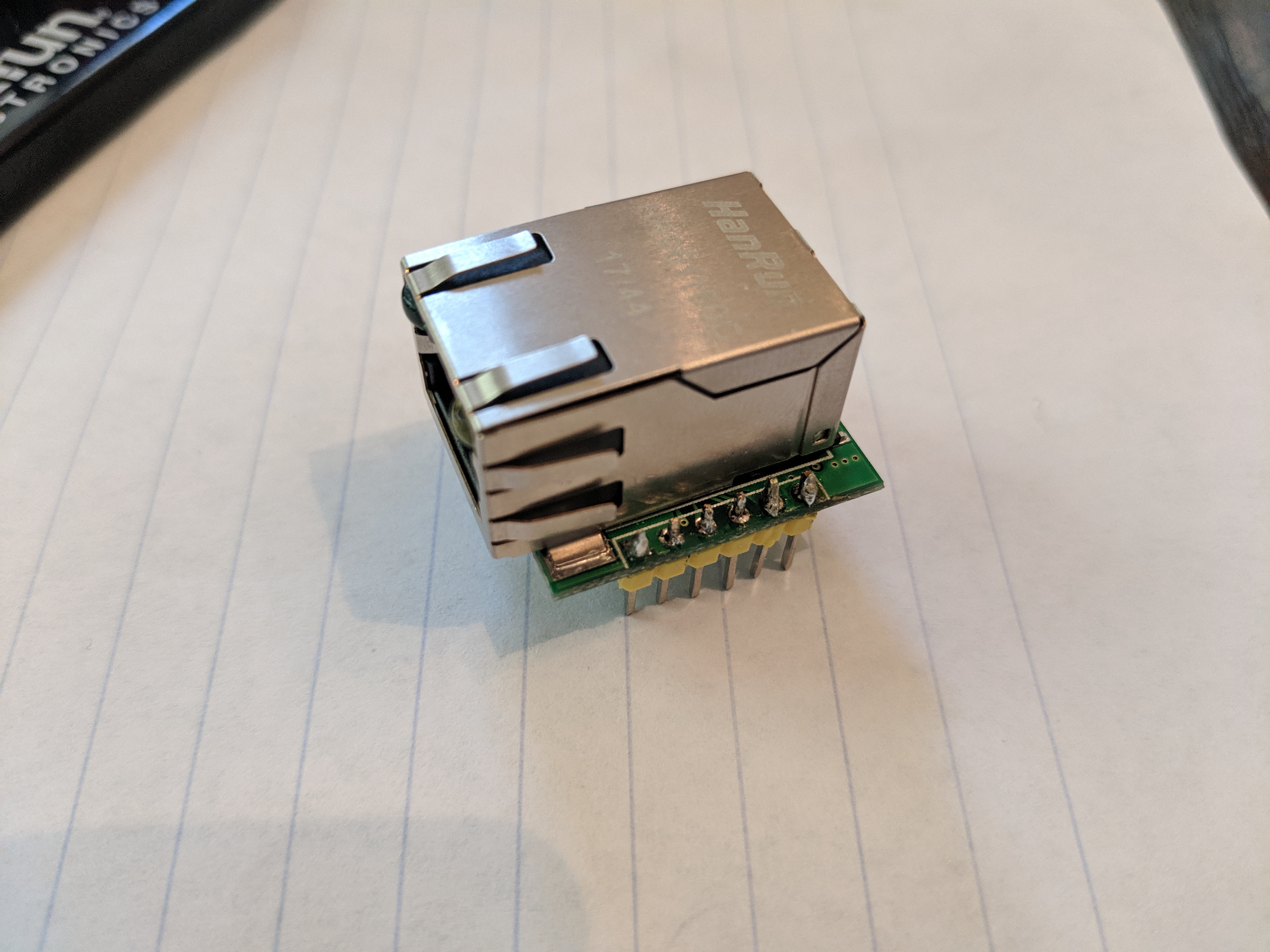
Finally, the part I ordered last month from China has come in. Specifically, the Mini Ethernet Board W5500 from Makerfabs. I need this part because I only have an Arduino Uno, which does not have Ethernet built-in. While I doubt I’ll be going with the WIZnet chip for the final product (it’s more expensive and has functionality I don’t need), my research indicates it’s a little better supported by the Arduino community (has an official shield) and should be easier to get started with.
Soon I will work on replicating the functionality of the 1.0 POC, but for now let’s just make sure the module works as expected. Unexpectedly, the module comes with the pins not attached to the board. That means soldering is required. As I’ve never soldered before, I asked a friend to bring his over and help teach me. Here’s the final product.
After soldering, I placed it onto a breadboard and wired it up based on a cross-reference between the board diagram on the product page, and a YouTube video I found about wiring a different W5500 module.
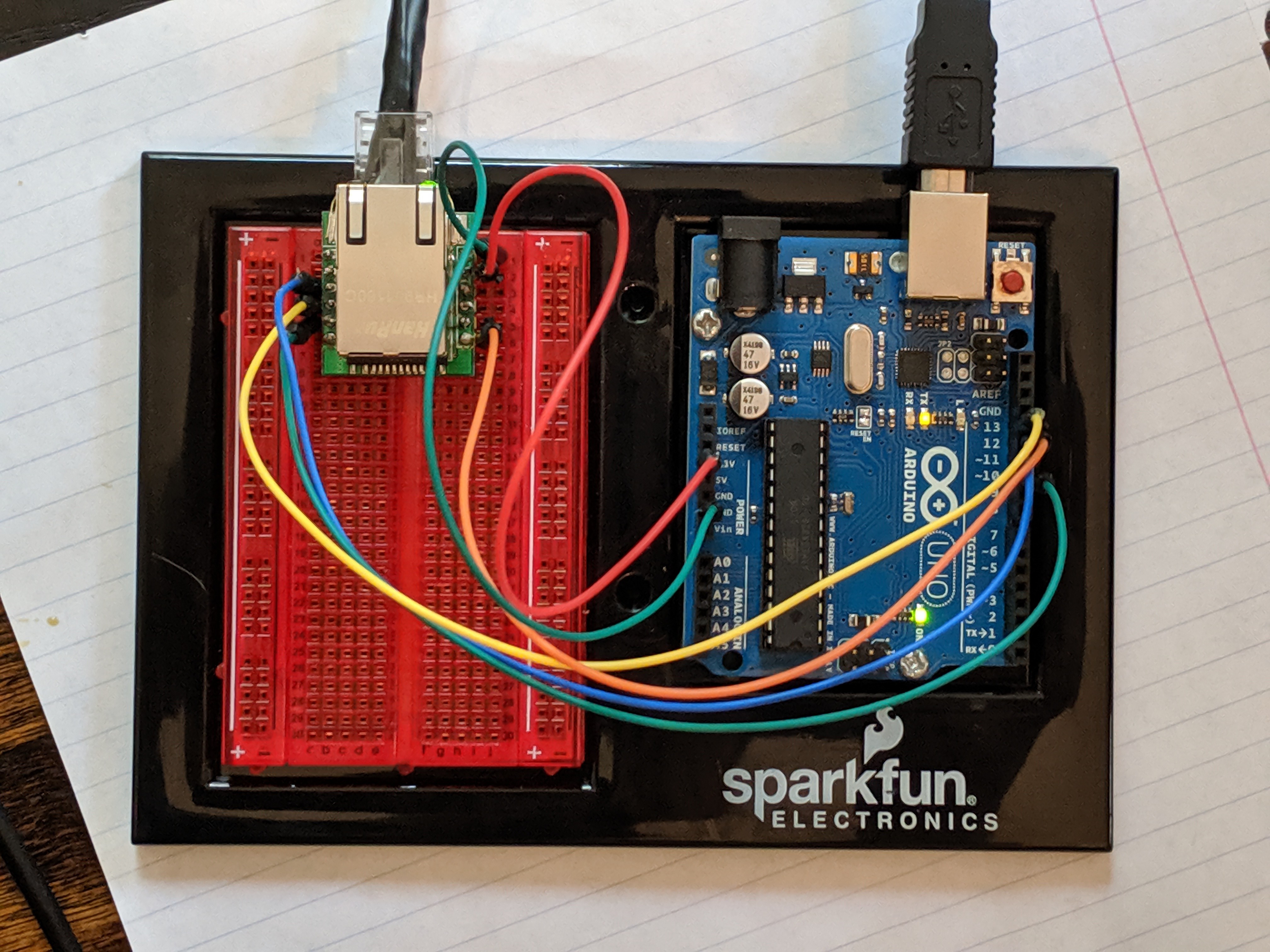
The exact wiring is:
| Arduino | Ethernet Board |
|---|---|
| 3.3V | 3V3 |
| GND | GND |
| ~11 | MOSI |
| 13 | SCLK |
| ~10 | CS |
| 12 | MISO |
To interface with the W5500 board, I used the official Ethernet library and a default sketch. Again, the task here is to ensure the board works as expected before I start messing with stuff.
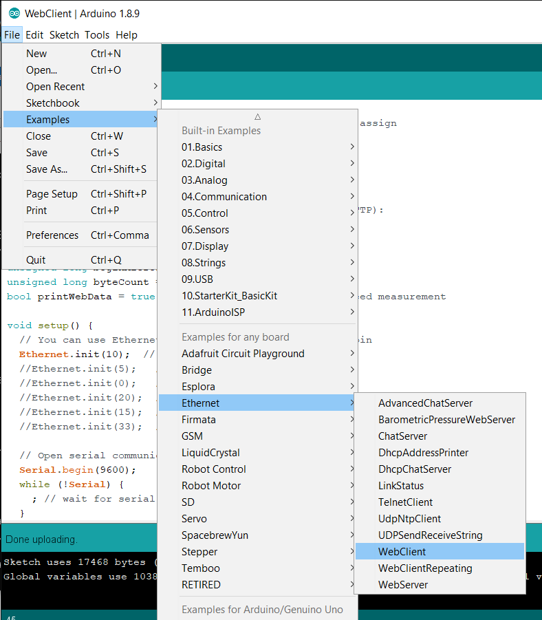
Only one tweak is necessary. The CS pin must be chosen. In this case, since I wired it to pin ~10, I can uncomment line 45.
Ethernet.init(10); // Most Arduino shields
Hit the Upload button, and the Serial Monitor shows the process of connecting to the network and downloading a Google search results page. Success!
Next up we’ll start re-implementing the real product’s behavior.
Next: 2019-07-14 — Rust on Arduino
